Don’t try to (needlessly) upsell me.

Writers, Print Vehicle Service Histories for Every Vehicle
read more
Don’t try to (needlessly) upsell me.
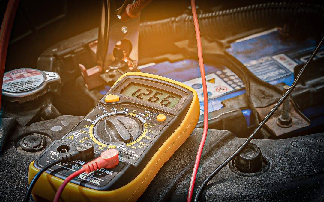
Whether you used a fuel pressure gauge or relied on the Fuel Rail Pressure PID on your scan tool, a reading of zero when testing fuel pressure is a bad thing. What are your next steps? Do you jump the relay to see if the pressure builds? Do you use an amp probe and a scope to current ramp the pump to gauge its condition?
If you’re dealing with a conventional brush-type pump, these methods may be OK, but if you’re dealing with a brushless DC fuel pump (BLDC), these methods may lead you to an incorrect conclusion.
To avoid mistakes that can lead you down the wrong diagnostic path, it’s important that you understand how the system and components work. When it comes to fuel delivery, vehicles may use a brush-type pump that runs continuously, or one that is controlled by an ECU using a duty-cycle voltage to control pump speed. Both are prone to wear over time. To address this, some manufacturers are opting for the brushless design and that one is a whole different ball game when it comes to testing.
In any brush-type DC fuel pump, there are numerous components inside the pump housing. Permanent magnets are attached to the inner case, and there’s a rotor comprised of coils of wire. There are typically eight of these coils with the ends terminating at commutator strips. Two carbon brushes, one supplying system voltage and the other circuit ground, are in contact with the commutators, 180 degrees apart from each other. When power is supplied to the circuit, the coils are energized, and a magnetic field is created.
The poles of these fields are in opposition to the poles of the permanent magnets so the two try to push away from one another. This begins the rotation of the rotor. The connection in that one winding is soon lost, though. However, the next commutator soon takes the place of the first, ensuring that the strength of the magnetic opposition continues.
A brushless DC motor has no brushes or commutators to wear out. In its simplest terms it is a brushed motor built inside out. The permanent magnet parts of the motor are located on the armature, and windings are now attached to the outer case. This stator only has three coils, connected in either a “Y” or “Delta” winding similar to an alternator’s stator.

This is a cutaway view of a brushless DC fuel pump. The stator windings are phased 120 degrees apart and there are no mechanical parts to wear. Photo: Delphi.
A dedicated fuel pump control module pulses voltage through each of the three windings sequentially 120 degrees of rotor rotation apart. This is also known as a three-phase motor design. It simulates the AC voltage needed to operate the motor by switching polarity of the applied DC voltage. Speed is controlled by adjusting the duty cycle of the pulsed power supply.
The end result is the same as we’ve seen in a brush-type pump. Each coil, in turn, builds and collapses a magnetic field and it’s the resulting magnetic opposition between the stator and the rotor that gets the pump moving.
Let’s see what all this looks like on a scope. Using the wiring schematic, we can identify that the pump is a brushless design by the presence of the three stator connections, typically labeled just as they are on a hybrid or EV motor/generator with the letters U, V and W. We’ll connect a scope channel to each and use the last channel to monitor current flow through one of the stator windings.

Notice the fuel pump pinouts on this wiring diagram for a late model Toyota. You can see that the pump has no power and ground for brushes, but has three pinouts for the U, V, and W stator windings. Photo: Mitchell 1.
You can see that if you attempted to measure current flow or voltage at the pump, you would only see the pulsed value of the Fuel Pump Control Module’s (FPCM) signal. If you didn’t know that this was a brushless pump, you may assume that the fuel pump wasn’t getting a good power supply or ground, or that there was an issue with the pump itself. That could lead to a costly mistake and the replacement of a component that was working just fine.
If you attempted to use the current ramping technique that we scope junkies have been using for years, you wouldn’t see anything similar to the pattern you are used to. Again, that could lead you to an incorrect diagnostic conclusion.

This is what the operation of the brushless DC pump looks like on a digital storage oscilloscope. It is easy to see the phased stator windings in operation. Note the current polarity switching from positive to negative. Photo: Peter Meier.
You can see on this sample capture how each stator is controlled in phase with the others, 120 degrees apart. If one of the coil windings was shorted internally or the circuit was open, the difference would be immediately apparent in the amplitude and shape of the pattern. You can also see the polarity switching in the current pattern on screen, demonstrating how the DC voltage supply is made to act like an AC voltage supply. This switching of polarity is necessary to keep the magnetic field poles aligned.
The testing methods you may be accustomed to using on a conventional pump do not apply to this style pump. Before you jumper that relay or break out your current probe, make sure you first confirm what type of pump is being used on the vehicle.
The articles and other content contained on this site may contain links to third party websites. By clicking them, you consent to Dorman’s Website Use Agreement.
They may look simple, but these little toggles can enable powerful electronic versatility.
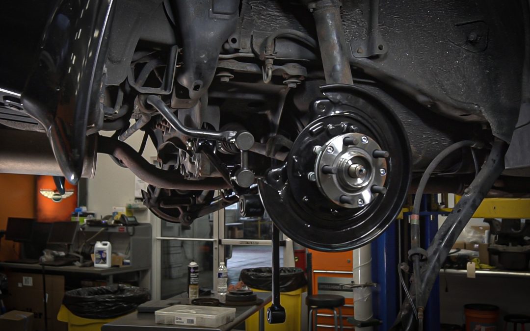
Loaded knuckles streamline wheel bearing and suspension repairs to help shops boost efficiency and profitability.

Can there be one threadlocker color to rule them all?

When it comes to threaded items, wrong is right. Or is it left?
To reach a successful diagnostic conclusion, you have to follow the right diagnostic path.

A bent dipstick and a broken oil cap are lucky indeed!
Participation in this forum is subject to Dorman’s Website Terms & Conditions. Please read our Comment Policy before commenting.